Workshop

Anodizing

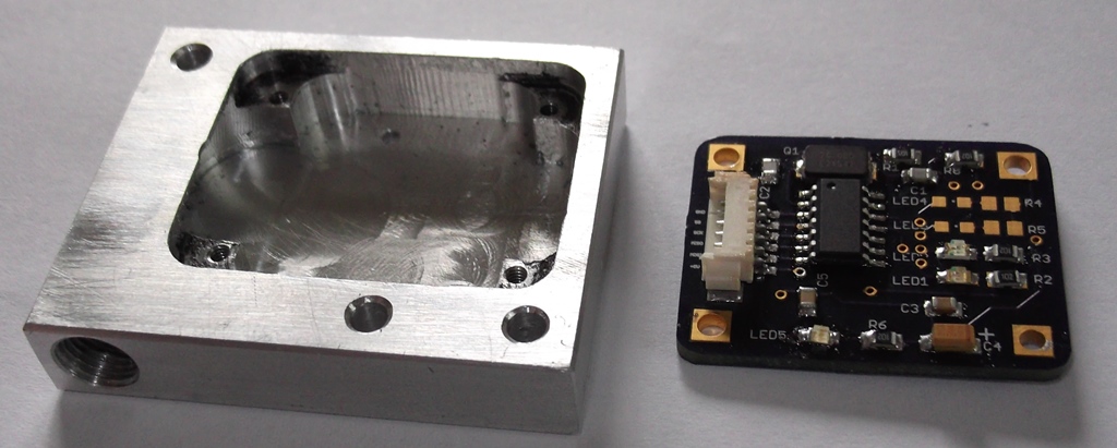
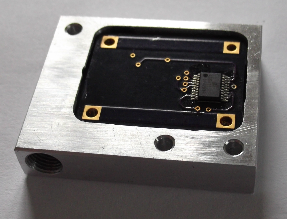
Sensor case looks like a good candidate for some home anodising….(or Anodizing if you are American)
You can do this pretty easily without acid and get pretty good results.
I’m in New Zealand… The nice caring authorities here don’t trust people like me with sulphuric acid needed for the usual methods. It’s not that easy to buy here. Never mind.. there are alternatives.

Sodium Bisulphate – commonly used to lower the PH of swimming pools. This is a salt of Sulphuric acid and for my purpose, will work fine.  Usual disclaimers here… I’m not responsible for any damage you do to yourself etc if you attempt this. Use common sense when using these chemicals.  This works for me.

Here’s how I do it.

First I make sure the aluminium is really clean and all those machining marks have been taken out. And when you think it’s really clean, clean it again.  I like to etch the aluminium in some Sodium hydroxide (NAOH, Drain cleaner) for a few minutes. A few teaspoons in a 1/2 litre of water is all you really need.  Sodium Hydroxide is nasty stuff on skin and eyes….cover them. I don’t soak it longer than about 5 minutes. This eats aluminium nicely.

sensor5
I wash in water taking care not to touch with my oily hands….

I use a piece of aluminium about 120mmx100mmx6mm thick for the cathode. I use a low current car battery charger. Mine is 2200ma capacity. This is more than enough for such small objects and finally a Sodium Bisulphate solution. I use about 1 part NaHSO4 to 4 parts water by weight. So about 200g disolved in 800ml water. Negative to the cathode, positive to the nicely cleaned case connected with some aluminium wire. Place them a few inches apart and let it bubble away for anything from 1 to 2 hours. Small hydrogen bubbles will be seen bubbling up from the cathode. Best done outside since hydrogen is of course flammable…..Here’s one of the cases being anodised. Current is about 250mA. (bubbles not really visible in the photo)

sensor7

So I have my newly anodised case. Time to dye it.
I’ve experimented with a number of dyes/inks. I’ve had varying degrees of success with black acrylic dyes and inks. Most of these give a blue or purple colour on aluminium. So black acrylic ink gives me any colour between purple and black depending on concentration. A bit of experimmentation is required here. For this, I’m using some ‘Pebeo colorex’ black ink.

I now use the ink non diluted. I apply it with a small brush. Providing your anodizing process has worked properly, this should soak up the ink almost instantly. If you can still see the metal after applying the ink, the aluminium is either not clean enough or hasn’t been anodized long enough. I then boil it for about 20 minutes in boiling water to seal.

You can remove the anodised coating if necessary by soaking it in Sodium Hydroxide again.

sensor6

Done.

Encoder boards and casings.

Ok. So while I’m waiting for the prototype display board to come back from the PCB Fab.,
I’ll spend some time on the enclosures for the encoder boards. I ended up redesigning the encoder
board to be slightly smaller and to use the Molex pico-blade connectors rather than a 0.1″ header.
I also changed the crystal case and dropped one of the LEDS I used originally on the index line.
Not much point in putting an LED on this line. It pulses every 2mm travelled for 1uS. Barely visible.

So here’s the encoder board – front and back.

sensor2 sensor1

LEDs and resistors for the A and B incremental lines are not installed. Nice to have them blinking away while testing, but otherwise pretty useless. LEDS installed for power and Mag Dec/Inc. these should be visible through some 1mm holes in the case.

For the enclosure/casing, I’ve used a piece of 10mm aluminium bar, milled a pocket for the PCB with four mounting points.
(using a 1/4″ end mill) The PCB sits 0.1″ from the surface, leaving the top of the sensor chip flush with the surface.
Once the PCB is installed I’ll encase it in resin, leaving the sensor chip flush with the top.
There’s probably not much point in actually installing the LEDS on the sensor board unless you plan to make them visible
through a few small holes. The LEDS were useful when testing the code.

Here’s the case…

sensor3 sensor4

After many magic words to assist in crimping the pico-blade connectors on a test lead (these are small!), I’m not sure I will continue using these. Maybe a few holes in the PCB and the wires mounted directly is the best way to go. Once the board is epoxied in place, it won’t be going anywhere.

While I have tapped the mounting holes M2, I probably won’t use these except for temporarily mounting of the board before potting in epoxy.

Encoder case looks like a good candidate for some home anodizing….and since the main PCB still hasn’t turned up, that’s next…

Prototype 1

The prototype encoder PCB has been made and tested with an Arduino Nano.

You will notice in the photo that I’m using 7 segment displays and a small OLED display.

I plan to support a number of different displays. One version with the ‘traditional’ 7 segment displays and one version with a large OLED display showing all data. I tend to favour the OLED displays. They have low power consumption, fantastic contrast, excellent refresh rate and easy to use.

proto1

The LED display shown in the photo is connected via SPI. The display board is based on the MAX7221. Current per segment has been limited to less than 5mA per segment since I’m powering it from the USB port.

The small 1″ OLED is connected via I2C so only requires two I/O ports on the Arduino.  This particular board is labelled ‘CRIUS’ and used on multicopter controller boards commonly available off Ebay for a few bucks. If you buy one of these CRIUS boards, make sure you buy the version 1.2 board. The earlier boards don’t work well with the Arduino without modification.(adding a resistor/capacitor on the reset line). I used the U8glib library for this display.

The 300mm magnetic strip for the encoder is visible at the bottom of the breadboard.

Code needs to be refined more with X,Y,Z axis and reset/unit switches.  Hopefully this will fit in the Arduino ATMega328 code space.

Next prototype will use a 2.4″ green I2C OLED display based on the SSD1305 controller. This display is 128×64 pixel and should be big enough to display all X,Y,Z readings with a metric or imperial unit indicator. Unfortunately this display isn’t current supported by the U8glib library. It is very similar to the SSD1306 based displays so should be easy enough to modify the library.  Waiting on a Display PCB to arrive to test this….

DIY Digital readouts

I have a few machines in my home workshop. I guess most people like me have found that the cost of the machine is small compared to the accessories you need… So I spend most of my time making accessories. I’d like some digital readouts for my machines. Problem is that they cost lots for lots of machines… Why not make some. How hard can it be? Magnetic scales seem to be the easiest way to go for the serious DIY’er Small in size, scalable to any size simply by cutting the magnetic strip and of course, relatively cheap. Austrian Micro Systems make a range of linear encoders suitable for this project. I’ve picked the AS5311 device. This device has a resolution of about 0.5um. It also has quadrature output that provides a resolution of 1.95um 1.95um is good enough for me. 0.00195mm So, how am I going to read these devices? The Arduino was my first thought. Cheap and easy to program. The Quadrature output of the AS5311 gives 1024 pulse per 2mm magnetic pole pair. I want my project to have at least 3 axis capacity. I don’t think the Arduino would cope with this on three separate inputs. After some searching for quadrature counters, I came across the LS7366R from LSI. This is a 32bit Quadrature counter with a SPI interface. Perfect. So, my sensor consists on an AS5311 and a LS7366R to count the pulses. Then, it’s just a matter of reading the pulse counter on the LS7366R and displaying the results. This should allow me to use the Arduino to process the counts and drive a display. Here’s my circuit: Encoder Circuit board time.