Ok. So while I’m waiting for the prototype display board to come back from the PCB Fab.,
I’ll spend some time on the enclosures for the encoder boards. I ended up redesigning the encoder
board to be slightly smaller and to use the Molex pico-blade connectors rather than a 0.1″ header.
I also changed the crystal case and dropped one of the LEDS I used originally on the index line.
Not much point in putting an LED on this line. It pulses every 2mm travelled for 1uS. Barely visible.
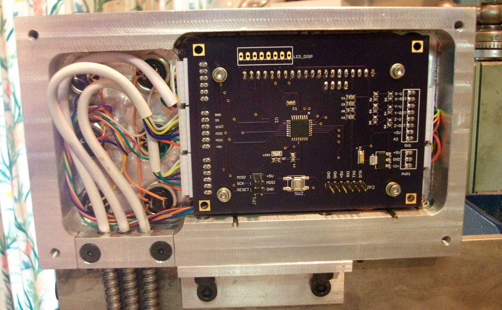
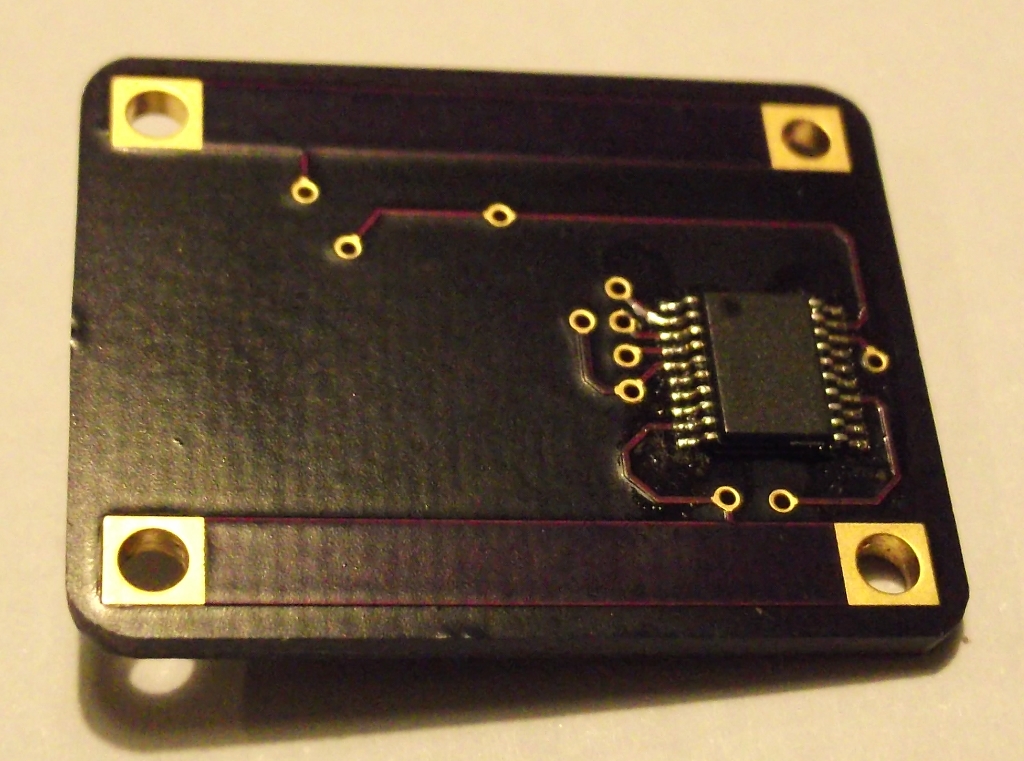
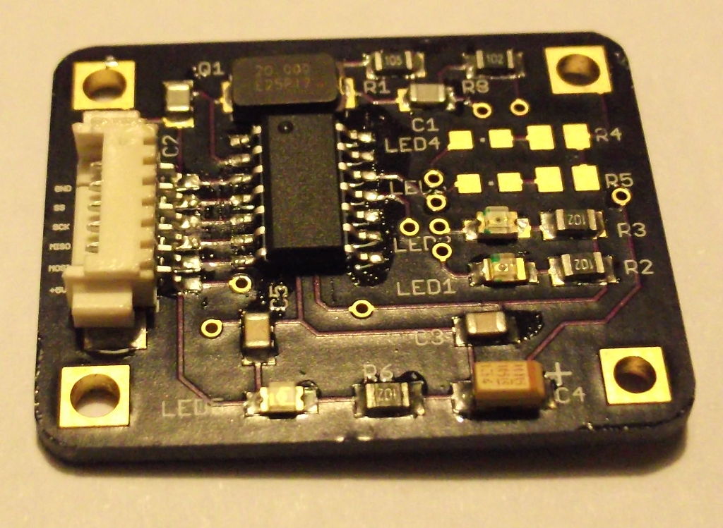
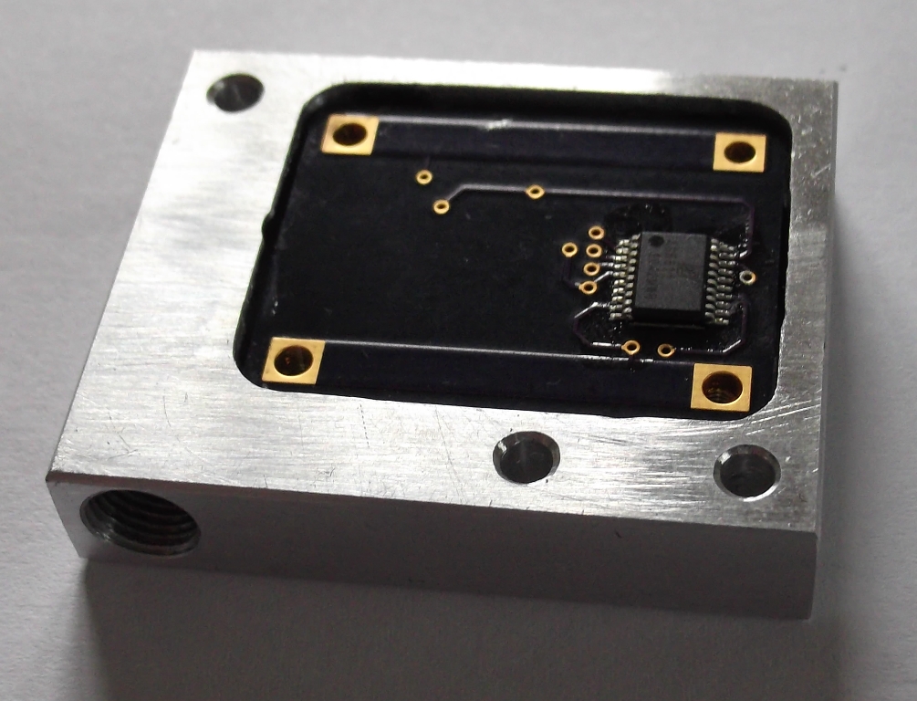
So here’s the encoder board – front and back.


LEDs and resistors for the A and B incremental lines are not installed. Nice to have them blinking away while testing, but otherwise pretty useless. LEDS installed for power and Mag Dec/Inc. these should be visible through some 1mm holes in the case.
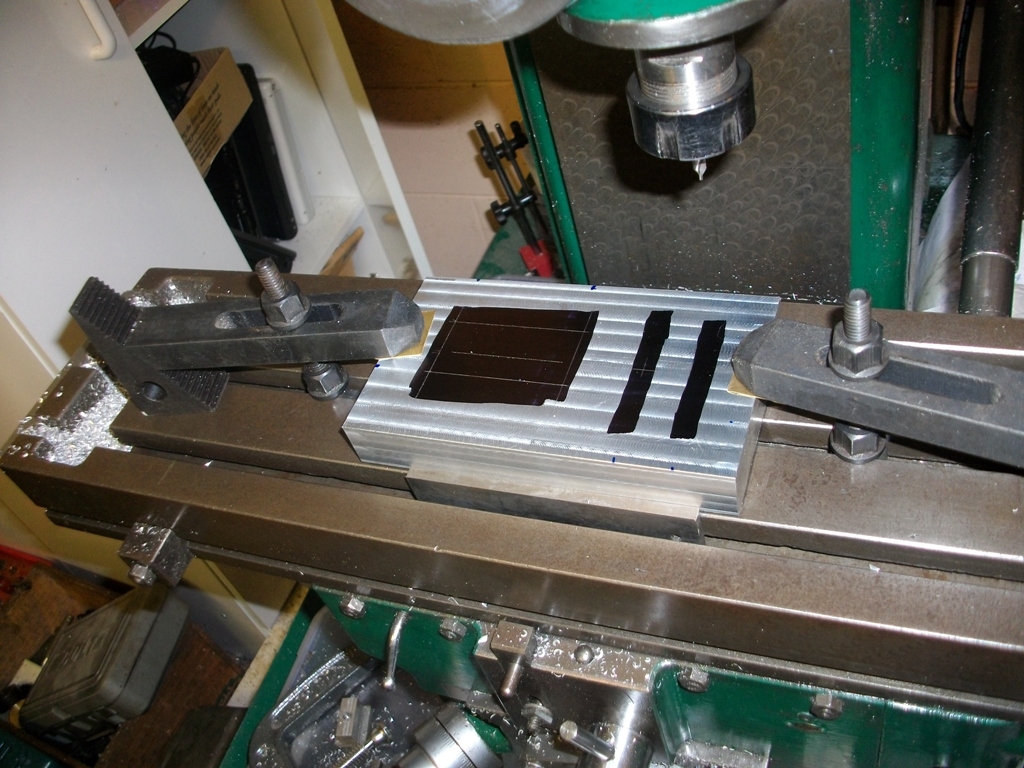
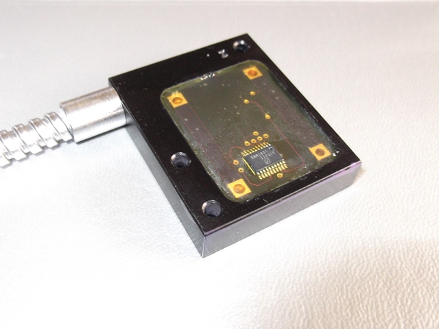
For the enclosure/casing, I’ve used a piece of 10mm aluminium bar, milled a pocket for the PCB with four mounting points.
(using a 1/4″ end mill) The PCB sits 0.1″ from the surface, leaving the top of the sensor chip flush with the surface.
Once the PCB is installed I’ll encase it in resin, leaving the sensor chip flush with the top.
There’s probably not much point in actually installing the LEDS on the sensor board unless you plan to make them visible
through a few small holes. The LEDS were useful when testing the code.
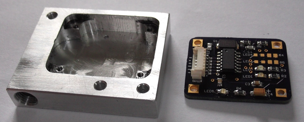
Here’s the case…


After many magic words to assist in crimping the pico-blade connectors on a test lead (these are small!), I’m not sure I will continue using these. Maybe a few holes in the PCB and the wires mounted directly is the best way to go. Once the board is epoxied in place, it won’t be going anywhere.
While I have tapped the mounting holes M2, I probably won’t use these except for temporarily mounting of the board before potting in epoxy.
Encoder case looks like a good candidate for some home anodizing….and since the main PCB still hasn’t turned up, that’s next…