Another Toy. I have purchased a small CO2 laser cutter/engraver.
After a bit of research, I decided on a Chinese made ‘K40D’ type machine.
The advantage of this model over the more common ‘K40’ is the addition of a linear slide on the X axis and built in air assist. The air assist has the benefit of keeping your optics free from smoke deposits.
With a bit of modification these cheap machines can be made quite useful.

To me, the biggest issues are the fixed Z axis – requiring the bed to be manually moved to get the correct focus and the need to always be attached to a PC to operate. Here’s a brief description of the mods I’ve done to correct this.
The Z axis.
With the standard bed removed there about 70mm between the focus point and the bottom of the metal case. Others have solved this problem with a adjustable single stepper motor and belts/cogs.

While browsing one of my favourite sites, I came across some hollow shaft NEMA 17 stepper motors. My Z axis design evolved from these.
The motors are bored 6.1 mm. Four motors mount on each corner of a 40mm aluminium frame should do the trick. Unfortunately, these motors are 5 wire with a common centre tap on the windings meaning that the only way to drive them is in unipolar mode. Probably the reason they are only about US$6.50 each…
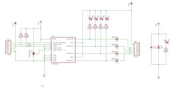
We can get around this by using the UCN5804LB motor driver chip. While it is now obsolete, there are still plenty available and it is very easy to use.
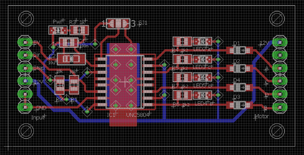
I created a small PCB to for this. One for each motor.
These will be fed common Step/Direction signals. I also wanted a push button up/down setup so created a driver board to able to manually drive these or also accept a control signal from the new off-line controller that I plan to install next.
A small amount of addition logic was added to opto-isolate, buffer the signals and effectively disconnect the direction control line from the controller when using manual mode.
The motors draw about 0.22A per winding at 12V so well within the 5804’s 1.25A limit.
The board also has a jumper to select ‘wave’ mode driving two windings at the same time for increased torque. (At the expense of increased current draw)
Here’s quick drawing of the setup (motors are attached to the top section, threaded rods attached to bottom section)
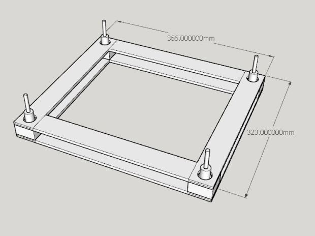
The motor’s shaft is 8mm. A brass threaded coupling was turned up to fit this as shown in the sectioned view below. (Excuse the quick and dirty CAD) Threaded coupling is then attached with loctite to stepper shaft.

Four threaded rods approx. 120mm in length screwed into the base complete the design.
If you reproduce this, good accuracy is required between the centres on the threaded rod and stepper shaft centres.
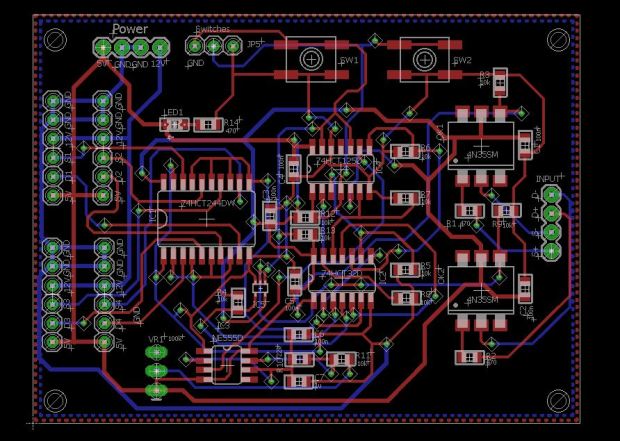
The control board:
And schematic:

The board mounted switches are for testing. The switch connections are broken out on a three pin header for manual control.
The basic frame is made from 40x6mm aluminium extrusion lapped at each corner.
Two opto-isolated inputs are provided for Step/Direction signals from a new laser controller board or alternatively, control can be manual with your existing laser control board.
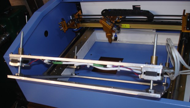
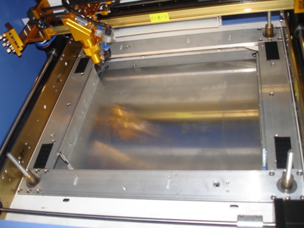
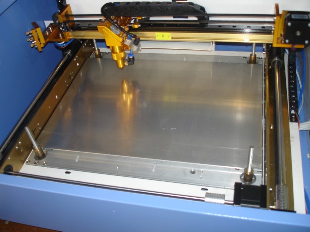
The new axis has two separate beds. One as shown above giving maximum available height and one shown below with the bed at the standard level.
While the 2mm Aluminium plate is not the ideal bed being highly reflective, I will probably replace with some sort of metal mesh once I find something thin enough.
Electronics design files can be found here: https://github.com/pcm52/K40-Laser-Z-Axis
To house the electronics, I machined some 13mm Al Plate on the CNC mill.

Next – the new off-line controller.
