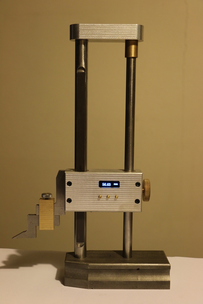
The current madness in the world has given me the chance to spend more time updating some designs. I’ve been meaning to update the DRO files for a while now. Here’s the first part of the latest versions.
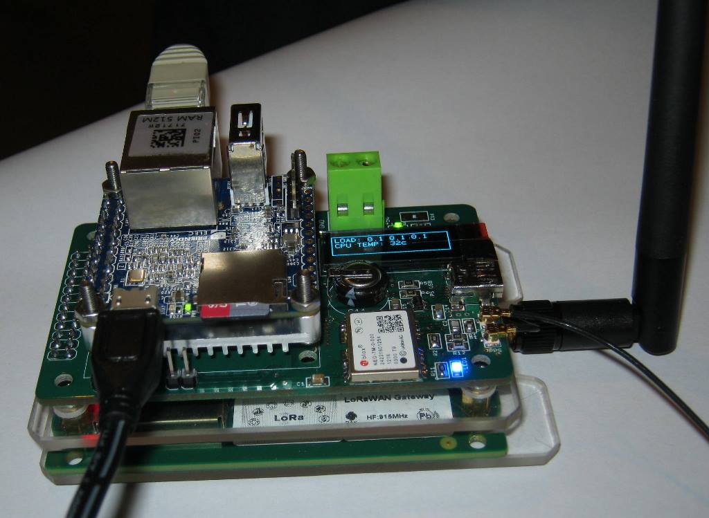
Starting with the single axis display.
This is another ATMega328p based board so you can treat it like an Arduino Uno. My previous designs have used the LS7366 Quadrature counter IC to off-load the pulse counting task from the 328p. It’s possible to count pulses with the ATMega328p PROVIDING you don’t try and count them too fast. I’ve made this optional on this board. There are two solder jumpers -SJ1 and SJ2, that switch the A + B quadrature signals to either an optional LS7366 OR the two ATMega328p interrupt pins D2 and D3. Options shown below:

Using the interrupts will work quite well providing you don’t try and move an axis faster than about 70mm/sec. More than this and it will skip steps. If you want to move the axis faster than this, then install the LS7366 on the PCB. (I recommend using the LS7366 in any case)
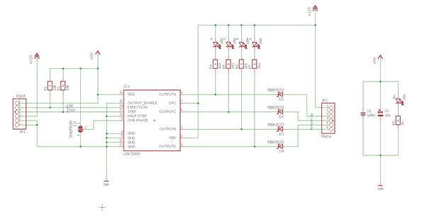
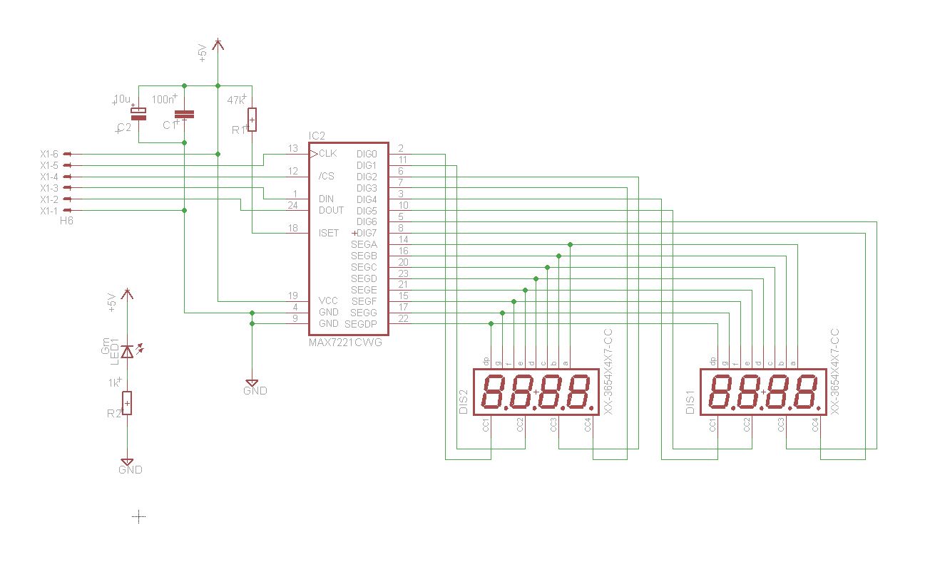
Here’s the circuit:

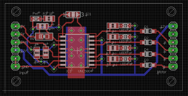
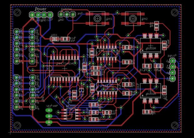
And the layout:

Note that a 20 MHz crystal is shown on the schematic for the LS7366. For best performance use a 40MHz. I used what I had at the time.
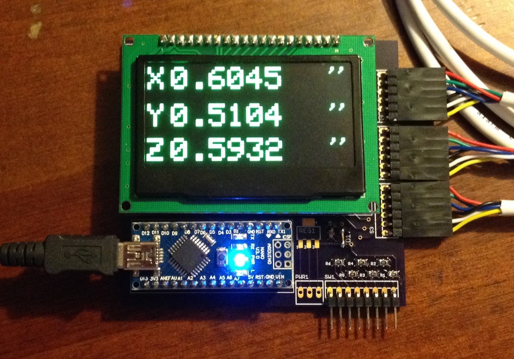
The board supports either a SSD1309 1.5” 128×64 or SSD1305 2.2” 128×32 OLED displays. Other than this, you can use any other I2C display connected to the 4-pin header provided on the board.
A count reset and Unit (mm’s or inches) Toggle switch inputs are provided via the D4 and D5 pins on the PCB. There’s also a standard ICP connector with the Reset/SPI bus pin for installing the bootloader.
Finally, I got sick of using FTDI adapter boards to load sketches, so I’ve included an FT232RL for USB connection.
Eagle Schematic and layout files with the code can be found here:
https://github.com/pcm52/DRO-V6
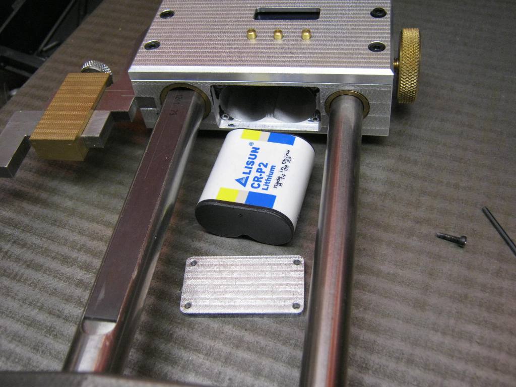
The DRO requires a 4 wire connection to the AS5311 sensor board – A + B quadrature signals and GND and +5V.
Here’s the sensor board circuit:
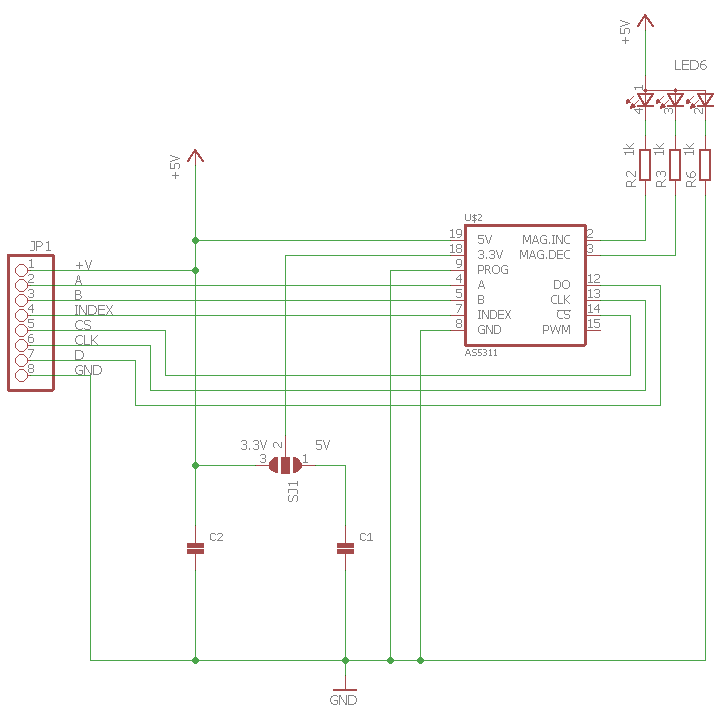
I’ve made this a general purpose board that breaks out all the AS5311 outputs should you wish to experiment or feel brave and write your own code for the serial interface to try and get that 0.5um resolution. I’ll stick to the 1.95um resolution that’s offered using the quadrature signals.
Note that the CS pin on the PCB needs to be pulled low to enable the encoder.
I’ll make the boards available at least in bare PCB form shortly. Maybe a small production run of built up boards depending on interest.
Example code uses the U8g2 Display library and Paul Stoffregen’s Encoder library for the interrupt version.
Next – the 3 Axis board….coming soon.